


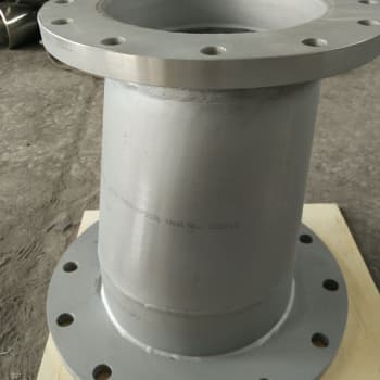
A pipe spool is a prefabricated section of piping, complete with flanges, fittings, valves or weld ends, cut and welded in a shop to the dimensions of an isometric drawing, and delivered to site ready to be bolted into place.
The reason buyers pay for spool fabrication instead of cutting pipe in the field is simple: shop fabrication moves the skilled work, the welding, the inspection and the hydrostatic testing out of the construction schedule and into a controlled environment, and it compresses weeks of field labor into a single lift.
But the entire value of a spool is destroyed if the dimensions are wrong. A spool that is 4 mm too long does not fit between two flanges; a flange rotated one bolt hole out of position takes hours to correct on a live line.
This page covers the tolerance system that governs pipe spool fabrication, the welding practice behind it, and the data a buyer should put on the RFQ so that the spools arrive at the project site and drop into place.
The fabrication standard most often named on spool drawings is ASME B31.3, the Process Piping code, which sets the weld-quality requirements, while dimensional tolerances are commonly taken from PFI ES-3, the Pipe Fabrication Institute standard for fit-up and dimensional control, or from the project specification. In practice the numbers used across the industry are consistent, and they are the numbers in the tables below.
Why shop fabrication beats field fabrication on cost and quality
The economic case for pipe spools is made in three numbers: weld productivity, inspection access, and schedule compression. A welder in a shop with a positioner and power source rated for the job completes a butt weld in roughly half the time of the same weld at height on a scaffold. Every weld in a shop can be radiographed, hydrostatically tested, and repaired under controlled conditions before it ships.
And because spools are made in parallel while civil work proceeds on site, the critical path of the project shortens by the length of the fabrication cycle. The buyer pays a shop premium for the spool itself, and the project pays back several times over in reduced site labor, reduced scaffold and crane hours, and fewer weather delays.
Quality is the second reason. In a shop the welder works on a positioner, the joint fit-up is checked with the pipe aligned in a fixture, the weld is made in the most favorable position, and the finished weld is inspected with the pipe on the bench rather than up a column. The reject rate on shop welds is consistently lower than on field welds, and a rejected shop weld is repaired while the spool is still in the shop, not after it has been erected.
The dimensional tolerance system: the numbers that decide fit-up
Dimensional control on a spool starts with the isometric drawing. Every spool has a spool number, and every dimension on the drawing carries a tolerance band. The values below are the industry-standard bands applied to spool fabrication, consistent with PFI ES-3 and common project specifications:
| Dimension | Typical tolerance | What it governs |
| Face-to-face length (flange to flange) | ±3 mm (±1/8 in) | The overall spool envelope; the most loaded dimension on the drawing |
| Center-to-center and center-to-face lengths | ±3 mm | Run lengths between branch centers and end flanges |
| Location of branch connections | ±3 mm | Branch take-off positions along the run |
| Flange bolt-hole rotation | ±1.5 mm at bolt circle | Whether the flange bolts line up with the mating flange on site |
| Flange squareness (tilt) | 1 mm per 200 mm of flange diameter | Flange face perpendicularity to the pipe axis |
| Misalignment at circumferential welds, NPS 24 and smaller | 1.6 mm max internal/external | Weld root alignment between pipe, fitting, or flange ends |
| Misalignment at circumferential welds, NPS 26 and larger | 3.2 mm max | Heavy-wall large-bore joints |
Two of these rows cause most of the site problems. The flange bolt-hole rotation tolerance is the one buyers forget to state: a flange welded 5 mm off its clock position means the studs cannot pass through the mating flange, and the correction on site is a re-drilled hole or a replacement flange.
The flange squareness row matters wherever the spool bolts to a pump, a valve, or a vessel nozzle, because a tilted flange face introduces bending stress into the equipment nozzle when the joint is pulled up. Stating both numbers on the RFQ, rather than leaving the fabricator to apply their own defaults, is the cheapest insurance in the whole spool purchase.
It is important to note that these tolerances are not cumulative. A spool that is +2 mm at the first weld and +2 mm at the second is still inside the ±3 mm envelope only if the fabricator controls each dimension from the datum point on the drawing, not by chaining tolerances along the spool. The drawings and the inspection procedure should state the datum end from which all dimensions are measured.
Welding, shrinkage, and the cut-length compensation
Spool fabrication is welding work, and welding shrinks metal. A single-pass butt weld on thin-wall stainless pipe may close the joint by 1-2 mm; a multi-pass weld on heavy-wall carbon steel can shrink 3-4 mm along the axis. A fabricator that cuts every pipe to the drawing dimension and then welds will produce a spool that is short by the sum of the weld shrinkages.
Experienced shops compensate by adding the measured shrinkage allowance to each cut length, and by making the fit-up dimension, not the cut dimension, the controlled dimension. The drawing dimension applies to the finished spool between the flange faces, and the shop controls it with a dimensional check at the fit-up stage and again after welding.
Welding processes on spools follow the material and the code. Carbon steel spools are welded with GTAW root and SMAW fill in the field-quality range, or FCAW where the project allows. Stainless and nickel-alloy spools are GTAW throughout, with matching filler and controlled interpass temperature, and no preheat is required for austenitic grades.
All welds are made by welders qualified to ASME Section IX, and the welding procedure specifications (WPS) are qualified by the same route. For critical services the welds are 100% radiographed; for standard process services the project typically specifies a percentage of RT with PT on the root and cap passes.
After welding, each spool is visually inspected, dimensionally checked, and then pressure-tested. The hydrostatic test pressure is normally 1.5 times the design pressure for the piping class, applied per the project specification, and the spool is held at test pressure long enough to verify the joints.
Where hydro testing is not possible, a pneumatic test at reduced pressure is used with the required safety precautions. The tested spool is then cleaned, the ends protected, and the flange faces covered before shipping.
End preparation and flange assembly
The ends of a spool are either flanged, beveled for field welding, or plain, and each end type has its own control points. Flanged ends require the flange to be square to the pipe axis within the 1 mm per 200 mm rule, the bolt holes rotated to the clock position on the drawing, and the flange face protected from weld spatter and mechanical damage.
Beveled ends require the bevel angle, root face, and included angle to match the field joint design, and the bevel is normally inspected with a profile gauge before the spool ships. The inside of the pipe at the weld ends should be free of scale and moisture, because the field welder will not re-prepare the end; they will fit up against exactly what the shop delivered.
On flanged spools, the flange-to-pipe weld is a full-penetration butt weld for most pressure classes, made with the flange tacked and checked for squareness before the root pass. The fabricator's fixture holds the flange against a true plane while the weld is made, and the finished joint is checked again after cooling. This is the step where the tolerance rows in the table above are actually enforced, and it is the step a buyer should ask about when qualifying a new fabricator.
Inspection and documentation
A spool shipment is accompanied by the same documentation package as any fabricated piping: the welding certificates and WPS/PQR records, the material mill certificates for pipe, fittings, and flanges, the dimensional inspection report, the hydrostatic test certificate, and the weld inspection records including RT film or digital reports where required.
For export orders, the certificates are issued per EN 10204 3.1 or 3.2, and third-party inspection by SGS, BV, or TUV is arranged on request. The dimensional report is the document that proves the spools will fit, and it should list every dimension on the drawing with the as-built measured value, not just a statement that the spool is "within tolerance".
Positive material identification (PMI) is recommended on receipt for alloy spools, because the difference between 316L and 316, or between 2205 and 2507, is not visible. Where the spools are made from dual-certified material, the certificates should state the dual designation so the site QC can match the material to the drawing.
What to put on the RFQ: the ten data points that prevent every dispute
A complete spool RFQ is short and dense. The following ten items, stated explicitly, remove nearly all the ambiguity that produces site problems and commercial disputes:
- Spool isometrics or GA drawings, with spool numbers, dimensions, and the datum end defined
- Material specification per line: pipe standard and grade (e.g. ASTM A312 TP316L), fitting standard (B16.9), flange standard (B16.5 class and facing)
- Design code and piping class (e.g. ASME B31.3, class 150# RF)
- Dimensional tolerances: state ±3 mm linear, bolt-hole rotation, and flange squareness, or name PFI ES-3
- Welding requirements: WPS/PQR, welder qualifications, and RT percentage
- Test requirements: hydrostatic test pressure and hold time, or pneumatic
- End finish: bevel type, flange facing, thread protection
- Marking and identification: spool number stenciling, paint color per line, material stamp
- Documentation: EN 10204 3.1 certificates, dimensional report, test certificates
- Packing and shipping: crating, end caps, flange covers, and the delivery schedule tied to the project sequence
Most spool disputes trace back to one of these ten items being left out of the RFQ and filled in by default. The buyer who writes the tolerance rows explicitly, and the fabricator who returns a dimensional report against the drawing, have already eliminated the two most common causes of field rework.
FAQ
Q: What is the standard length tolerance for a fabricated pipe spool?
A: The industry standard is ±3 mm (±1/8 in) on face-to-face and center-to-face dimensions for spools up to roughly NPS 10, with some specifications allowing ±5 mm on large-bore spools above NPS 10. State the value on the RFQ rather than relying on the fabricator's default.
Q: Why does flange bolt-hole rotation tolerance matter?
A: A flange welded out of its clock position will not accept the studs of the mating flange, and the correction on site costs far more than the rework in the shop. The standard tolerance is ±1.5 mm at the bolt circle, and it should be written on the drawing.
Q: Does welding change the length of a spool?
A: Yes. Each weld shrinks the joint by roughly 1-4 mm depending on wall thickness and pass count. Experienced fabricators add a shrinkage allowance to the cut lengths and control the fit-up dimension so the finished spool meets the drawing dimension.
Q: What tests are performed on fabricated spools before shipping?
A: Visual inspection of all welds, dimensional inspection against the drawing, hydrostatic testing at the specified test pressure, and the project's percentage of radiography or other NDT. The test certificate and dimensional report ship with the spools.
Q: Can spools be made from duplex and nickel alloys?
A: Yes. Spools are fabricated in stainless, duplex, and nickel alloys including 2205, 2507, Inconel, Monel, and Hastelloy grades. The WPS, filler metal, and interpass control must match the material, and the shop should be qualified for the alloy family.
Q: What documentation should arrive with a spool shipment?
A: The dimensional inspection report, hydrostatic test certificate, weld records and WPS/PQR references, material certificates for pipe, fittings and flanges, and the NDT reports. For export orders the certificates are issued per EN 10204 3.1 or 3.2.


